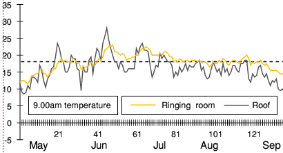
 On Sunday morning, service ringing is from 8.50 to 9.30. The graph shows the temperature at 9.00am every day, ie shortly after ringing starts.
| The problem | The solution | Pictures |
This was the final part of the project. Air conditioning was the only practical way to prevent excessive over heating in the summer. It was planned to be installed at the same time as the screen, since although the screen prevented overheating in the winter, enclosing the room on its own would make the summer problem worse. But approval of the air conditioning was delayed pending more supporting evidence. The ringers knew subjectively how bad conditions could get during ringing, but that was subjective and needed objective information to support it.
Temperature and humidity had been monitored over a period of several years, with sensors located in the ringing room and various other places (including the tower roof to monitor outside temperature) and this was extended to monitor conditions after the screen was installed.
The graphs below were extracted from the data recorded during summer 2017. They show the ringing room temperature (orange) and outside temperature (black) for each day at the three times when ringing would start. Both temperature and humidity rise significantly during ringing because of the heat and perspiration of active bodies in an enclosed space, so by the end of the session it would typically be between 2°C & 4°C hotter than it was at the start.
On Sunday morning, service ringing is from 8.50 to 9.30. The graph shows the temperature at 9.00am every day, ie shortly after ringing starts.
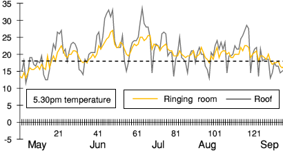 On Sunday evening, service ringing starts at 5.30 on weeks when there is a quarter peal and at 5.50 otherwise, and finishes at 6.30. The graph shows the temperature at 5.30pm every day.
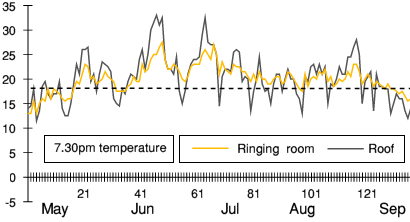 The regular weekly practice is from 8.00 to 9.30, and is usually preceded by a training session starting at either 7.00 or 7.30. The graph shows the temperature at 7.30pm every day.
The dotted line on the graphs at 18°C is the temperature above which ringing becomes uncomfortable. This is subjective, but it is broadly consistent with CIBSE guidance for comparable activities. As the graphs show, the ringing room is often hotter than this, and quite a lot hotter on many days.
The graphs also show that the outside air was often hotter than inside (about 30% of days at 5.30 & 7.30). That's because the inside of large stone buildings heat up relatively slowly over many days.
When the project began around 2000, air conditioning was much less common, but by 2020 it was widespread, with units available for homes as well as commercial properties.
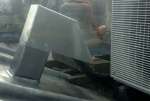
The unit installed is in two parts, one in the ringing room and the other on the tower roof. The internal unit extracts heat from the air in the room and the external unit ejects it outside as hot air. behind the parapet. Coolant circulates between the two, with cool fluid flowing down one pipe and hot fluid up the other.
The internal unit is high on the wall so the air can spread out and avoid draughts. The external unit is behind the parapet, near the clock bell, where it will not get walked past. The cables come through a special duct with a cowl to prevent any rain getting in.
Cooling the warm, moist air in the ringing room generates condensation, which is collected inside the unit and then pumped up alongside the coolant pipes to an outlet on the roof in the rain water gutter. The pump is halfway up the pipe, in the clock room where it can easily be accessed.
Like most modern air conditioning units, this one can run in reverse to provide heating in the winter (using much less electricity than using an electric fan heater.
The installation was by Coolserv .
Click each to enlarge and move between pictures using the arrows
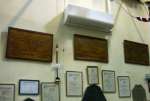 Internal unit in the ringing room |
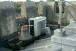 External unit on the tower roof |
 Cable and pipe ducts |
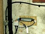 Condensate pump |
| Back to top | Back to Restoration project | Backward to Fitting the screen | Return to Home page | Feedback |